Creating Network Diagrams with JavaScript
Posted on October 02, 2019
- and tagged as
- cisco,
- javascript
I had a bit of spare time and wanted to mess around with Cisco’s NeXt UI Toolkit, a JavaScript library which, amongst other things, provides functionality for generating network topology diagrams.
Once we download and extract the library from the Cisco site, we’ll have 4 folders: css, doc, fonts, and js. From here we can start building a diagram.
Alternatively, the toolkit can be installed via npm; npm install next-ui.
HTML Template
All we need is a simple HTML page that loads the JS and CSS library files, provides a div for the diagram to sit in, then loads our topology data (which is just a JS object) and the app.js script which uses the library and topology data to generate the network diagram.
index.html
<!DOCTYPE html>
    <head>
        <link rel="stylesheet" href=css/next.css>
        <script src="js/next.js"></script>
    </head>
    <body>
        <div id="topology-container"></div>
        <script src="toplogy.js"></script>
        <script src="app.js"></script>
    </body>
</html>
Topology data
We need to provide two arrays, one for the list nodes (our network devices), and a second for the links between the nodes.
Nodes array
Each devices in the nodes array is an object with some common properties. Each node is identified by a unique id property that is used for creating links.
We then need to provide x and y coordinates for where the device will sit in the diagram. Following this is the name of the device.
The device_type property is a custom property, that is, it’s not in the NeXt UI API, but it is used in our app.js to define the icon the node should have. A list of icons can be found on the official Cisco demo page.
Finally, we optionally provide a property that defines the colour of the node in the diagram.
Links array
The links array also consists of objects, with each object being a link between two devices. The links objects only require source, target, and optionally, color properties.
topology.js
const topologyData = {
    nodes: [
        // ISPs
        { id: 0, x: 400, y: -100, name: "ISP1", device_type: "cloud", color: "grey" },
        { id: 1, x: 600, y: -100, name: "ISP2", device_type: "cloud", color: "grey" },

        // Routers
        { id: 2, x: 400, y: 0, name: "Edge1", device_type: "router", color: "red" },
        { id: 3, x: 600, y: 0, name: "Edge2", device_type: "router", color: "red" },

        // Switches
        { id: 4, x: 400, y: 100, name: "Switch1", device_type: "switch" },
        { id: 5, x: 600, y: 100, name: "Switch2", device_type: "switch" },

        // Servers
        { id: 6, x: 200, y: 200, name: "ESX1", device_type: "server" },
        { id: 7, x: 400, y: 200, name: "ESX2", device_type: "server" },
        { id: 8, x: 600, y: 200, name: "ESX3", device_type: "server" },
        { id: 9, x: 800, y: 200, name: "ESX4", device_type: "server" },

        // SAN
        { id: 10, x: 500, y: 300, name: "SAN", device_type: "server" }
    ],
    links: [
      // WAN to routers
      { source: 0, target: 2, color: "green" },
      { source: 1, target: 3 },

      // Routers to switches
      { source: 2, target: 4, color: "green" },
      { source: 2, target: 5 },
      { source: 3, target: 4 },
      { source: 3, target: 5 },

      // Switches to Switches
      { source: 4, target: 5 },
      { source: 4, target: 5 },

      // Servers to Switches
      { source: 6, target: 4, color: "green" },
      { source: 6, target: 5, color: "red" },
      { source: 7, target: 4, color: "green" },
      { source: 7, target: 5, color: "red" },
      { source: 8, target: 4, color: "green" },
      { source: 8, target: 5, color: "red" },
      { source: 9, target: 4, color: "green" },
      { source: 9, target: 5, color: "red" },

      // SAN to Switches
      { source: 10, target: 4, color: "red" },
      { source: 10, target: 4, color: "red" },
      { source: 10, target: 5, color: "red" },
      { source: 10, target: 5, color: "red" }
    ]
};
JS Application
Finally we need to write some JavaScript to pull it all together, most of the code below is taken from the Cisco tutorial files with some modifications.
app.js
(function(nx){

	// instantiate next app
	const app = new nx.ui.Application();

	// configuration object
	const topologyConfig = {
        // configuration for nodes
        width: window.innerWidth,
        height: window.innerHeight,
		nodeConfig: {
			label: "model.name",
            iconType: "model.device_type",
            color: "model.color",
		},
		// configuration for links
		linkConfig: {
            linkType: "straight",
            color: "model.color"
		},
		// if true, the nodes' icons are shown, a dot is shown instead
		showIcon: true,
	};

	// instantiate Topology class
	const topology = new nx.graphic.Topology(topologyConfig);

	// load topology data from app/data.js
	topology.data(topologyData);

	// bind the topology object to the app
	topology.attach(app);

	// app must run inside a specific container. In our case this is the one with id="topology-container"
	app.container(document.getElementById("topology-container"));

})(nx);
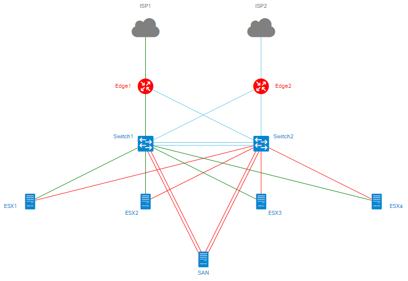
The result
The above three files gives us the network diagram below.
Documentation
The API documentation can be found here.