Cisco Policy Based Routing
Posted on March 07, 2014
- and tagged as
- cisco,
- networking
The following can be used to split traffic between two WAN links. It is typically used to provide a mechanism to route based on source rather than destination or to split different types of traffic across different links.
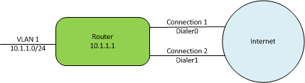
The above diagram illustrates the network used in this example. There is a single LAN connection through VLAN1, and two WAN connections, connected through Dialer0 and Dialer1. The goal will be to
1. Route all traffic sourced from an internal server at 10.1.1.40 through
Dialer0
2. Route all outbound rsync traffic from an internal server at 10.1.10.50
through Dialer1
3. Route all other HTTP/S traffic through Dialer1
4. Set the default route to Dialer0
PBR is implemented using the following steps
1. Create route maps to define traffic flow
2. Create ACLs to use with route maps
3. Apply route map to internal LAN facing interface
Create route maps to define traffic flow
route-map pbr-01 permit 10
 match ip address pbr-01-10
 set interface Dialer0
!
route-map pbr-01 permit 20
 match ip address pbr-01-20
 set interface Dialer1
!
route-map pbr-01 permit 30
 match ip address pbr-01-30
 set interface Dialer1
!
route-map pbr-01 permit 100
 set interface Dialer0
Notice the bottom route map entry (100) defines the default route. If this is not required, any traffic not defined in the route-maps will be routed using the normal routing rules (routing table)
Create ACLs to use with route maps
Sample ACLs below:
ip access-list extended pbr-01-10
 permit ip host 10.1.10.40 any

ip access-list extended pbr-01-20
 permit tcp host 10.1.10.50 any eq 873

ip access-list extended pbr-01-30
 permit tcp any any eq 80
 permit tcp any any eq 443
If there are GRE Tunnels in place, the above ACLs should deny traffic destined to private IP ranges else the traffic will be forwarded through the Dialer interfaces instead of the Tunnel.
Apply route map to internal LAN facing interface
interface Vlan1
 ip policy route-map pbr-01
The default route on the above configuration has the 0.0.0.0 0.0.0.0 route pointing to Dialer1. If the default route is ‘correct’ with other configurations the last route map (100) may not be required.
For NAT over dual links, the following has been used
ip nat inside source route-map NAT-OVERLOAD2 interface Dialer0 overload
ip nat inside source route-map NAT-OVERLOAD1 interface Dialer1 overload

route-map NAT-OVERLOAD1 permit 10
 match ip address nat.overload
 match interface Dialer1

route-map NAT-OVERLOAD2 permit 10
 match ip address nat.overload
 match interface Dialer0

ip access-list extended nat.overload
 remark --- deny nat for private addresses ---
 deny   ip 10.1.1.0 0.0.0.255 10.0.0.0 0.255.255.255
 deny   ip 10.1.1.0 0.0.0.255 172.16.0.0 0.15.255.255
 deny   ip 10.1.1.0 0.0.0.255 192.168.0.0 0.0.255.255
 deny   ip 10.1.1.0 0.0.0.255 127.0.0.0 0.255.255.255
 deny   ip 10.1.1.0 0.0.0.255 169.254.0.0 0.0.255.255
 deny   ip 10.1.1.0 0.0.0.255 224.0.0.0 31.255.255.255
 deny   ip 10.1.1.0 0.0.0.255 240.0.0.0 15.255.255.255
 remark -- permit local subnet --
 permit ip 10.1.1.0 0.0.0.255 any